Introduction

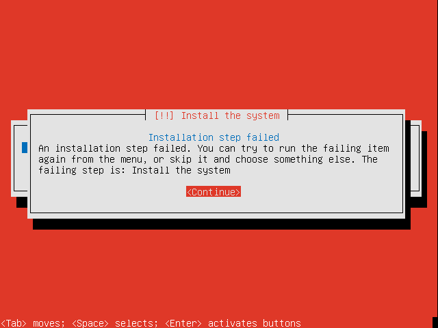
While working in a lab environment recently I wanted to vMotion a VM between two ESXi hosts. The vMotion failed, which was not entirely unexpected, due to CPU incompatibilities. These particular ESXi hosts are not in a vSphere cluster so enabling EVC (Enhanced vMotion Compatibility), which would resolve the issue, is not an option.

Attempting to vMotion a VM from host A to host B gave errors about:

  • MOVBE
  • 3D!Now PREFETCH and PREFETCHW

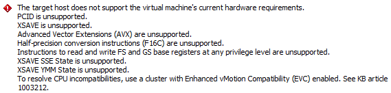
After powering the VM down, migrating the VM to host B and powering on, an attempt to vMotion from host B to host A gave errors about:

  • PCID
  • XSAVE
  • Advanced Vector Extensions (AVX)
  • Half-precision conversion instructions (F16C)
  • Instructions to read and write FS and GS base registers
  • XSAVE SSE State
  • XSAVE YMM State

Manual VM CPUID mask configuration

As the error messages indicate, Enhanced vMotion Compatibility (EVC) would enable the vMotion to take place between mixed CPUs within a cluster. Mixing host CPU models within a vSphere cluster is generally considered bad practice and should be avoided where possible. In this instance, the hosts are not in a cluster so EVC is not even an option.

As indicated above shutting down the VM and doing a cold migration is possible. This issue only relates to the case where I want to be able to migrate running VMs between hosts containing processors with different feature sets.

For the two hosts in question, I know (based on the EVC processor support KB and Intel ARK and VMware KB pages) that the Intel “Westmere” Generation baseline ought to be the highest compatible EVC mode; one of the processors is an Intel Avoton C2750 and the other is an Intel i7-3770S Sandy Bridge. The Avoton falls into the Westmere category for EVC. We will come back to EVC later on.

I suspected it would be possible to create a custom CPU mask to enable the vMotion between these to hosts. In general, features supported by a given processor are exposed via a CPUID instruction call. By default, VMware ESXi manipulates the results of the CPUID instructions executed by a VM as part of the virtualisation process. EVC is used to further manipulate these feature bits to hide CPU features from VMs to ensure that “well behaved VMs” are able to run when migrated between hosts containing processors with different features.

In this instance, “well behaved VMs” refers to VMs running code which use the CPUID instruction to determine available features. If the guest OS or application uses the CPUID instruction to determine available processor features then, when moved via vMotion to a different host, that same set of features will be available. If a guest uses some other mechanism to determine processor feature availability (e.g. based on the processor model name) or merely assumes a given feature will be available then the VM or application may crash or have other unexpected errors.

So back to this experiment. Attempting to go from host A to host B indicated only two feature incompatibilities. I turned to the Intel developers manual (64-ia-32-architectures-software-developer-vol-2a-manual.pdf) for the detail about the CPUID instruction. CPUID called with EAX=0x80000001 results in the PREFETCHW capability being exposed at bit 8 in ECX. Similarly with EAX=0x1, the MOVBE capability is exposed at bit 22 in ECX.

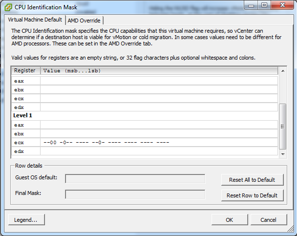
As an initial test, I did a cold migration of the VM to host A and edited the VM settings as shown below.

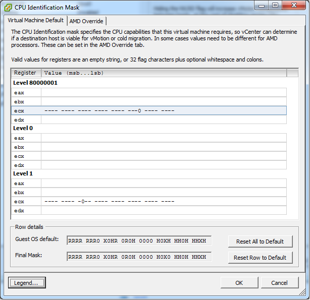
In summary, this is passing the CPUID result of the host via the above mask filter. The mask filter can hide, set or pass through a CPUID feature bit. In this instance I am hiding the two bits identified above through the use of the “0” in those bit positions. There are other options you can use as displayed in the legend.

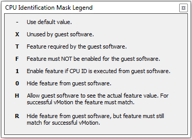
I chose “0” rather than “R” as I need to hide the feature from the guest OS and I do not care if the destination host actually has that feature or not.

I saved this configuration and powered on the VM. I was able to successfully perform a vMotion from host A to host B. I was also able to vMotion the VM back to host A.

I performed a vMotion back to host B and powered the VM off. I then powered the VM back on on host B. I tried to vMotion to back to host A, which again failed with the same error as shown above. The reason it failed in the reverse direction is that the VM pickups up it’s masked capabilities at power on and maintains that set of capabilities until it is powered off once more. So by powering on the VM on host B, it got a different set of capabilities to when it was powered on on host A. This explains why when attempting to originally perform the vMotion we had two different sets of errors.

To get the masks to enable a vMotion from host B to host A, I took a look at the developers guide and performed some Googlefoo, I identified the CPUID bits needed to mask the unsupported features:

PCID: CPUID EAX=1, result in ECX bit 17
XSAVE: CPUID EAX=1, result in ECX bit 26
AVX: CPUID EAX=1, result in ECX bit 28
F16C: CPUID EAX=1, result in ECX bit 29

FSGSBASE: CPUID EAX=7, result in EBX bit 00

XSAVE SSE: CPUID EAX=0xd, result in EAX bit 01
XSAVE YMM: CPUID EAX=0xd, result in EAX bit 02 (YMM are 256-bit AVX registers)

The first four are easy as the vSphere client allows one to edit the EAX=1 CPUID results. With the below configuration in place, the vMotion from host B to host A only showed the last three errors (FSGSBASE, XSAVE SSE and XSAVE YMM). This is expected as no masking had been put in place.

To put the masking in place for EAX=0x7 and EAX=0xd we need to edit the virtual machine’s .VMX file. We can do this by editing the .vmx file directly or by using the Configuration Parameters dialogue for the VM under Options/Advanced/General in the VM’s settings dialogue. The following two parameters (first one for FSGSBASE and second for the XSAVE) were added:

cpuid.7.ebx = -------------------------------0
cpuid.d.eax = -----------------------------00-

Powering on the VM succeeded, however the vMotion to host A failed with the same error about FS & GS Base registers (but the XSAVE errors were gone). Surprisingly when I checked the .vmx directly and the cpuid.7.ebx line was missing. For some reason it appears that the VI client does not save this entry. So I removed the VM from the inventory, added that line to the .VMX directly and then re-registered the VM.

I was now able to power on the VM on host B and vMotion back and forth. I was not able to do the same when the VM was powered on on host A. I needed to merge the two sets of capabilities.

At this stage we would have the following in the .vmx file:

for host A -> host B:
cpuid.80000001.ecx = "-----------------------0--------"
cpuid.1.ecx = "---------0----------------------"

for host B -> host A:
cpuid.1.ecx = "--00-0--------0-----------------"
cpuid.7.ebx = "-------------------------------0"
cpuid.d.eax = "-----------------------------00-"

(Note that there are some default entries which get added which are all dashes, and one for cpuid.80000001.edx with dashes and a single H).

We merge our two sets of lines to obtain:

cpuid.80000001.ecx = "-----------------------0--------"
cpuid.1.ecx = "--00-0---0----0-----------------"
cpuid.7.ebx = "-------------------------------0"
cpuid.d.eax = "-----------------------------00-"

At this stage we can now power on the VM on either host and migrate in either direction. Success. Using these four lines of config, we have masked the specific features which vSphere was highlighting as preventing vMotion. It has also shown how we can hide or expose specific CPUID features on a VM by VM basis.

Manual EVC Baseline Configuration

Back to EVC. The default EVC masks can be determined by creating a cluster (even without any hosts) and enabling EVC. You can then see the default masks put in place on the host by EVC. Yes, EVC puts a default mask in place on the hosts in an EVC enabled cluster. The masked off CPU features are then not exposed to the guests at power-on and are not available during vMotion compatibility checks.

The default baselines for Westmere and Sandybridge EVC modes are shown below:


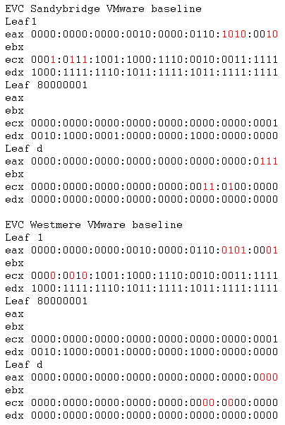
The differences are highlighted. Leaf1 (i.e. CPUID with EAX=1) EAX result relates to processor family and stepping information. The three Leaf1 ECX flags relate to AES, XSAVE and TSC-Deadline respectively. The three Leafd EAX flags are for x87, SSE and AVX XSAVE state. The three Leafd ECX flags are related to maximum size needed for the XSAVE area.

Anyway I’ve digressed. So the masks which I created above obviously only dealt with the specific differences between my two processors in question. In order to determine a generic “Westmere” compatible mask on a per VM basis we will start with VMware’s ESXi EVC masks above. The EVC masks are showing which feature bits are hidden (zeros) and which features may be passed through to guests (ones). So we can see which feature bits are hidden in a particular EVC mode. So to convert the above EVC baselines to VM CPUID masks I keep the zeros and change the ones to dashes. I selected dashes instead of ones to ensure that the default guest OS masks and host flags still take effect. We get the following for a VM for Westmere feature flags:

cpuid.80000001.ecx = "0000000000000000000000000000000-"
cpuid.80000001.edx = "00-0-000000-00000000-00000000000"
cpuid.1.ecx = "000000-0-00--000---000-000------"
cpuid.1.edx = "-000-------0-0-------0----------"
cpuid.d.eax = "00000000000000000000000000000000"
cpuid.d.ecx = "00000000000000000000000000000000"
cpuid.d.edx = "00000000000000000000000000000000"

I did not map the cpuid.1.eax flags as I did not want to mess with CPU family/stepping flags. Also, the EVC masks listed did not show the cpuid.7.ebc line I needed for the FSGSBASE feature. Sure enough, using only the 7 lines above meant I could not vMotion from host B to host A. So, adding

cpuid.7.ebx = "-------------------------------0"

to the VMX then allowed the full vMotion I was looking for. The ESXi hypervisor must alter other flags apart from only those shown on the EVC configuration page.

TL;DR

To configure a poor man’s EVC on a VM by VM basis for a Westmere feature set, add the following lines to a VM’s .VMX file.

cpuid.80000001.ecx = "0000000000000000000000000000000-"
cpuid.80000001.edx = "00-0-000000-00000000-00000000000"
cpuid.1.ecx = "000000-0-00--000---000-000------"
cpuid.1.edx = "-000-------0-0-------0----------"
cpuid.7.ebx = "-------------------------------0"
cpuid.d.eax = "00000000000000000000000000000000"
cpuid.d.ecx = "00000000000000000000000000000000"
cpuid.d.edx = "00000000000000000000000000000000"


Appendix

1

Useful thread -> https://communities.vmware.com/thread/467303

The above thread covers manipulating the guest CPUID. An interesting option is mentioned in post 9 relating to an option to enable further CPUID manipulation than is possible by default. In my tinkering above, I did not need this option.

monitor_control.enable_fullcpuid = TRUE

Note too that the vmware.log of any VM can be used to see the CPUID information of the host, as also mentioned in post 9:

As for extracting the results, you can write a program to query the CPUID function(s) of interest, or you can just look in the vmware.log file of any VM.  All current VMware hypervisors log all CPUID information for both the host and the guest

Post 13, again a user jmattson (exVMware now at Google), reveals a simple way to configure the processor name visible to guests:

cpuid.brandstring = "whatever you want"

2

This thread https://communities.vmware.com/thread/503236, again involving jmattson, discusses cpuid masks – and gives an insight into how EVC masks interact with the VM cpuid masks.

3

This post https://v-reality.info/2014/08/vsphere-vm-version-impact-available-cpu-instructions/ reveals that the virtual hardware version of a given VM also plays a role in the CPUID mask a VM is given. I found this interesting as it does give us another reason to actively upgrade the hardware versions of VMs.

4

A little gem is mentioned at the bottom of https://kb.vmware.com/selfservice/microsites/search.do?language=en_US&cmd=displayKC&externalId=1029785 – it seems that IBM changed the BIOS default for some of their servers. The option was changed to enable the AES feature by default. This resulted in identical servers configured with BIOS defaults, which were added to a vSphere cluster, having two different sets of CPUID feature bits set (AES enabled on some and disabled on others) resulting in vMotions not being possible between all servers.

I was doing a clear out of some paper work and came across these write performance tests which I did a few years back on an HP DL380 G5 with a p400 RAID controller.

  • 4 drive RAID10 = 144MB/s (~72MB/s per drive)
  • 4 drive RAID0 = 293MB/s (~73MB/s per drive)
  • 8 drive RAID0 = 518MB/s (~64MB/s per drive)
  • 8 drive RAID5 = 266MB/s (~38MB/s per drive)
  • 8 drive RAID6 = 165MB/s (~28MB/s per drive)
  • 8 drive RAID10 = 289MB/s (~72MB/s per drive)

The “per drive” is data being written per active data drive, excluding any RAID overheads.

I inferred from the above that the p400 RAID controller maxes out at around 518MB/s as it is unable to saturate 8 drives in a RAID0 array (64MB/s vs 72MB/s per drive). Not sure if this is a controller throughput or PCIe bus limitation.

Eitherway, this testing was (I think) done on Ubuntu 10.x or 12.x with pretty bog standard settings using a simple command such as:

dd if=/dev/zero of=/dev/cciss/c0d0 bs=1024k

I thought I’d capture these figures here since I have no where else to save them.

Just a reminder that there are reserved DNS domain names and reserved IP addresses for documentation purposes. These are detailed in RFC2606 and RFC5737 respectively.

The reserved DNS top level domain (TLD) names are:

  • .test
  • .example
  • .invalid
  • .localhost

.test is reserved and recommended for testing purposes within organisations. .example is reserved for use within documentation which requires example DNS names. .invalid should not be configured within resolvers and can be used when invalid DNS names are required for testing purposes. .localhost is traditionally been defined with an A record pointing at the locahost IP address of 127.0.0.1.

There are reserved second level domain names for documentation purposes of

  • example.com
  • example.net
  • example.org

The following three address ranges have been reserved for use within documentation where example IP addresses are required:

  • 192.0.2.0/24 (TEST-NET-1)
  • 198.51.100.0/24 (TEST-NET-2)
  • 203.0.113.0/24 (TEST-NET-3)


There are various posts relating to issues with VMware Workstation and the use of SATA physical drives (i.e. passing a physical SATA drive through to the guest VM).

The first challenge is getting past the “Internal Error” error message. To do so, create a VM with a SATA virtual disk. Once you’ve done this, you can try and add a SATA physical drive to the guest. This needs to be as a SATA device, since adding the pass-through drive as a SCSI device works. You will receive the “Internal Error” error message. Note that the .vmdk file is created for the drive in the VM’s directory.

The next step is to edit the .vmx and replace the original SATA device (sata0:0.fileName= line) with the newly created .vmdk file. This will get the SATA pass-through device into the VM. However, I was not able to power on the VM at this stage and got another error message.

Looking in the VM’s log file it was apparent that VMware Workstation was unable to open the raw device,
\\?\Volume{someGUID}

The fix to this is to run VMware Workstation as administrator. So instead of double clicking as you normally would, you need to right click and select “Run as administrator”. This was the step that I did not see mentioned anywhere else.

By doing this, I was able to start the VM and it then worked as expected!

This is just a short post about an annoying issue I encountered today while updating my automated Ubuntu installer with Ubuntu 14.04 (Trusty Tahr). I have a PXE based network boot process to automatically install and configure Ubuntu server instances. The server to be installed will PXE boot and then get the installation files and preseed configuration file via HTTP. This worked well for prior LTS releases.  I don’t bother with automating non-LTS releases as their lifespan is far too short for “production” use.

I updated the install server with the new 14.04 server images (AMD64 and i386). I then updated my standard preseed configuration file with the new paths to 14.04 and set off a server installation. Unfortunately, not long into the installation process an error message was displayed. “Install the system” was the title of message and the error was “Installation step failed” “An installation step failed. You can try to run the failing item again from the menu, or skip it and choose something else. The failing step is: Install the system”.

Error during a netboot install of Ubuntu 14.04

Not terribly useful, if I say so myself. Looking at the installation log on VTY-4 (accessed via ALT-F4 on the console), I saw messages about “main menu: INFO: Menu item ‘live-installer’ selected'” followed by “base-installer: error: Could not find any live images”. Again, not very useful.

To cut a long story short, after much time using Google, I found the solution. The way base Ubuntu is installed seems to have changed with Ubuntu 12.10 (Quantal Quetzal). It seems that rather than installing individual packages initially, a base preconfigured file-system is deployed. This is now contained in a file called “filesystem.squashfs” which is located at “/install/filesystem.squashfs” on the installation media. It seems that when installing via the network (in some situations), you need to configure the preseed file to use this “default” filesystem from the network. This is done in your preseed file by adding the “d-i live-installer/net-image” option, such as in the following line:

d-i live-installer/net-image string http://10.1.1.2/trusty-server-amd64/install/filesystem.squashfs

where 10.1.1.2 is your network installation server and /trusty-server-amd64 is the location of the installation media on the network installation webserver.

Once that is in place, you’re good to go! As I said before, this is only necessary since Ubuntu 12.10. As a result, all of those upgrading our installations from 12.04 LTS to 14.04 LTS may need to be aware of this. There is surprisingly little reference to this on the Internet. Do not many people install over the network in isolated install networks?


It is not often that I come across a tool which does something I’ve been trying to do for a long time. In this instance the tool is for PDF manipulation. This blog entry is primarily a reminder to myself of how to do this, but hopefully it will help someone else. Scanning documents and converting them to PDF files is fairly simple these days thanks to freebies such as Foxit Reader. However, for anything more complicated (page insertion, deletion, rotation, etc) I’ve always run into problems finding free tools. I do own an old copy of Adobe Acrobat, which can do many of these functions but it is on an old computer and I don’t seem to be able to move it thanks to Adobe’s licensing regime. In the past I’ve managed to find a variety of tools to do these one off PDF manipulations, say a merge of two documents, but no real “workhorse” tool or programme which is worth keeping around. However – today I found a real gem!

Some background. I’ve started scanning a variety of documents rather than keeping paper copies. Single pages are typically no problem, as described above. However, today I had the need to scan an A5 booklet formed of A4 sheets. Each printed portrait A5 page was half of a landscape A4 sheet. The page numbers of the booklet were as follows:

A4 sheet1:  A5 pages: 12 / 1 (reverse side: 2 / 11)
A4 sheet2:  A5 pages: 10 / 3 (reverse side: 4 / 9)
A4 sheet3:  A5 pages: 8 / 5 (reverse side: 6 / 7)

In the past, I tried to solve this type of task by cutting the A4 sheets in half and then scanning the resultant A5 sheets. This worked in a fashion but the scanner had reliability issues when feeding the A5 sheets. I figured there must be a better way. Turns out there is, and with a bit of Googling I found this.

Three free tools can accomplish what I want. These tools obviously need to be installed/available on your computer.

  • Foxit Reader – for the scanning of the document (any “scan to PDF” tool will be fine for this)
  • Briss – for cropping the scanned A4 PDF pages into A5 PDF pages
  • PDFtk – for rotating and reordering the PDF file’s pages – PDFtk Server (the command line tool) is described herein

PDFtk is the real gem which I found today. Super powerful and free!

The process to scan and process such a booklet and get a usable resulting PDF is as follows.

Remove any staples from the booklet and check the pages remain in order

This is fairly straight forward. Check the pages remain in order and that they will pass through the scanner without issues. Check for any wrinkles or bent corners. The key is to ensure that the pages scan as smoothly and repeatedly as possible.

Scan the double-sided A4 sheets

Using a typical tool, such as Foxit Reader, scan the double-sided A4 sheets, into a PDF titled ff1.pdf. I ended up with alternating upside down, rightside up sheets. So the PDF pages were as:

PDF page 1: pages 12/1 upside down
PDF page 2: pages 2/11 rightside up
PDF page 3: pages 10/3 upside down
PDF page 4: pages 4/9 rightside up
PDF page 5: pages 8/5 upside down
PDF page 6: pages 6/7 rightside up

Rotate the upside down pages

We need to get all the pages in the PDF file to be the correct orientation. This is a breeze with PDFtk. In my case, I used the following command line:

pdftk ff1.pdf cat 1south 2 3south 4 5south 6 output ff2.pdf

Reading the documentation further, I discovered that one could instead use:

pdftk ff1.pdf rotate oddsouth output ff2.pdf

This command rotates pages 1, 3 and 5  by 180 degrees and outputs the resulting PDF to ff2.pdf. We now have a PDF with the scanned pages correctly orientated but each PDF page consists of two A5 sheets:

PDF page 1 : pages 12/1
PDF page 2: pages 2/11
PDF page 3: pages 10/3
PDF page 4: pages 4/9
etc

Crop each A4 PDF page into a pair of A5 PDF pages

This is where the Briss tool works its magic. Briss enables PDF files to be cropped. In this case we want two crop regions on each PDF page. So we load ff2.pdf into Briss. We then define two crop areas on each page. Note that Briss overlays all even and all odd numbered pages so that only two crop definitions are required for multi-page PDFs. A single crop area is displayed by default for both the even and odd stacked pages. A second crop area can be created by clicking and dragging on the stacked pages. Carefully define two similar sized crop areas over the pair of A5 pages on each displayed A4 stack. Once the areas are defined generate the new PDF, ff3.pdf

Reorder the PDF pages

The resultant PDF, ff3.pdf, should now have all the pages as A5 looking pages but they will be out of order. In my case the PDF pages contained the following booklet page order: 12, 1, 2, 11, 10, 3, 4, 9, 8, 5, 6, 7

We turn again to PDFtk and run the following command:

pdftk ff3.pdf cat 2 3 6 7 10 11 12 9 8 5 4 1 output ff4.pdf

This creates a PDF file, ff4.pdf, with reordered pages. The first page in the new PDF was the second from the input PDF and so on.

Enjoy the completed PDF

We now have a completed PDF containing the individual pages from the booklet, all correctly ordered and rotated. A little bit of work, sure. But much easier than manually trying to scan each individual page.


A further comment. I think the PDFtk Server tool is fabulous. It is a command line tool and I can see myself returning to it time and again. It is seriously powerful with a vast array of options. I am sorry and amazed that I’ve not come across it before. There is a free GUI version available which isn’t as powerful and a paid-for GUI with a similar feature set.


Recently there has been a surge in the use of UDP amplification based distributed denial of service (DDoS) attacks on the Internet. So much so, that the US-CERT has issued a couple of advisories to highlight the issue. The are available at:

Firstly, some terminology.

  • Denial of service attacks are attacks against some infrastructure whereby the volume of traffic (in some cases legitimate) is used to overwhelm either the target device itself or upstream devices resulting in the target device being unable to provide “typical” or “acceptable” levels of service to the intended audience.
  • Distributed DoS attacks make use of a number of attacking machines as opposed to just one source. These attacking machines are generally hijacked PCs controlled by a “botnet” controller.
  • Spoofing is a technique whereby the source address in transmitted IP packets is not the IP address of the sending machine. It could be termed “computer identity fraud”, since the source address is typically faked, or spoofed, to be that of the target of an attack
  • UDP is “easy” to use for this class of attacks since it is connectionless and does not require a connection set-up handshake as TCP does.
  • Amplification attacks are attacks whereby an attacker can use the behaviour of a, typically an intermediary, host to generate more “reply” or “response” traffic than “attack” traffic. In other words, for each “attack” packet an attacker sends, the “amplifier” host generates multiple packets in response. These response packets are sent to the source address in the attack pack.

So, based on the above we can link the components together to explain this type of attack which is under way. Attackers are currently using their botnets to generate “attack” traffic, from multiple source machines, with the IP packets’ source address field containing the victim’s IP address. The traffic is sent to hosts which can be used to amplify the traffic. These hosts are typically, currently DNS or NTP servers. These servers generate multiple packets in response to a single “attack” packet. These reply packets are sent to the victim’s IP address, which is included in the attack packet. All these reply packets coming from multiple amplification hosts typically swamp the victim resulting in an unusable host.

Why is NTP used to do this? Well, in years gone by when the Internet was considered safer, various protocols had diagnostic and informational commands or options available to assist with troubleshooting or just to provide further information about a server’s status. One such option for an NTP server was that used by the ntpdc command “monlist”. This command returns information about all the recent clients which have communicated with an NTP server, and this list of clients can be quite long. Typically, one NTP query packet sent to an NTP server with the “monlist” command code can result in many packets in response. Since UDP is not connection orientated, the client and server do no initial handshake and hence the server “trusts” that the indicated source IP address of the query is actually the “real” source IP address. Unfortunately, attackers know this weakness and exploit it by spoofing the traffic with the victim’s IP address.

How can we avoid situations like this? Well, two simple things can be done to mitigate many of these attacks

  • Implement traffic filtering to limit IP address spoofing. Egress and, if possible, ingress filtering should be put in place as appropriate.
  • Limit publicly exposed IP based services – block or disable everything and enable on a port by port (case by case) basis. Ensure that those services which are exposed are configured securely and limit their functions to those necessary.

If “consumer” ISPs (i.e. ISPs providing service to end users) were to implement ingress filtering from their customers then many of these attacks would cease since spoofing would not be possible. If these same ISPs were to filter their egress traffic then their customers would only be able to spoof the address of other customers. I don’t understand why more ISPs do not implement proper filtering. Ingress and egress filtering has been mentioned for many years now, so I don’t understand why more ISPs don’t implement it. I do understand that carrier ISPs cannot always implement suitable filtering, but ISPs for end users should be able to!

The second point is more tricky. So many devices are exposed to the internet these days. NAT has limited the number of devices “directly attackable” from the outside, so we are lucky in that regard. However there are plenty of publicly accessible devices which are not configured correctly, either due to lack of interest, ignorance or error.

That last word “error” is what prompted me to write this post. Early this morning I started receiving some Nagios warnings about ping failures to one of my VPS servers. Given traffic limits on the VPS, I implemented rate filtering on the VPS to limit my exposure to unexpected traffic bills. Upon investigation I discovered that it was being used as an NTP amplifier. Hmm. Turns out, when I configured the VPS I had used

restrict default kod nomodify notrap nopeer nomodify

rather than

restrict default kod nomodify notrap nopeer noquery

OOPS! As a result the evil attackers out there were able to use the VPS to generate amplified traffic. Yes, there are IP filters in place, but this VPS did need to be exposed for NTP service unfortunately so couldn’t be blocked entirely. Needless to say, with the correct configuration in place the traffic levels have dropped off and the server is accessible once more.

So people, we need to be ever more vigilant on this big-bad Internet. Make sure traffic filtering is in place to prevent spoofing. Filter unnecessary traffic where possible. Configure services securely.


I got an e-mail letting me know that I had passed my VMware VCAP5-DCA exam. Phew! I sat the exam a week before Christmas, so the news after Christmas about my pass was a belated Christmas present!

The exam was pretty much as described by the various other blog postings. The main problem I faced was time. I ended up skipping some questions due to time constraints. I wrote 1-26 on the note board and ticked them off as I went along. I did each question as it popped up unless I was not confident on being able to complete it fairly quickly. This was going well until a question on the vMA.

The question in question was related to something I had not actually done in my prep but I figured I knew enough about the vMA to complete it. I ended up spending about 12 minutes to to get the question completed but didn’t manage to. Looking back, I should have decided to move on much sooner. This wasted time resulted in me not having sufficient time at the end to complete a question I could have.

The other “blunder” I made was related to a cluster configuration. After I read the question I knew what needed to be done. I went through and completed the question and moved on. A few questions later I was back doing something else cluster related and noticed that the previous configuration which I remembered doing was missing!! So, I back tracked the questions (you can in the DCA exam but not in the DCD) and re-did the prior question – this time ensuring I clicked OK and then verified the configuration was there. I guess the first time I must have clicked “cancel”  rather than “OK” in one of the dialogue boxes. Doh! So this effectively cost me another question worth of time.

I went into the exam being aware that I’d not spent enough study time on auto-deploy or image profiles. Needless to say questions related to those topics caused me to use more time than necessary. As I said previously, I ended up missing a few questions out due to time constraints. Had the remote connectivity been quicker and the exam environment been more responsive, I would have been able to do one or two more questions rather than waiting for screen redraws and so on. I’m not saying it was unusable, but more like being on the end of a slow WAN link (oh wait, the exam kit is hosted far away…). The frustrating thing was that for one of the questions my usual troubleshooting method would be to have a couple of windows open and flick between them fairly quickly, diagnosing the problem. Due to the exam environment this was not terribly feasible and I ended up skipping the question to make progress on other questions.

So, my “lessons learned” from this exam for any future DCA exams I might do are:

  • Be time concious and don’t get bogged down with trying to make something work unless you are certain that you have the knowledge needed to complete the question.
  • Know all the content of the blueprint fairly well. Read between the lines of the blueprint to know how the knowledge would be used in a real world situation. So, as an example do know the options for cluster fail over capacity and know how the options would relate to a real world requirements. Try and understand how the topics contained within the blueprint apply to solving day-to-day administrations problems or meeting platform requirements.
  • Read through the supporting documents mentioned in the blueprint. Try to read all the entire documents at least once to get plenty of additional background knowledge.
  • Ensure plenty of hands-on LAB time. Try and use the version of vSphere mentioned within the blueprint. Currently vSphere 5.0!
  • Try and enjoy the exam. It does not feel too much like an exam as you are doing hands on problem solving
  • Be time concious (yes, it is that important I mention it twice!)


So, how did I study for the exam? Well, I did hands-on exercises in a nested LAB environment under VMware Workstation (thanks VCP5!!). I covered the blueprint fairly extensively doing tasks based on activities mentioned in the blueprint. I also did “extra credit” type exercises where I tried to apply the knowledge from the topics for some real-world issues I’ve experienced and some hypothetical examples I thought up.

I read the following books:

I read loads of blog posts and followed numerous VMware related twitter peeps. Here are a few of the blogs/postings which I found useful while studying. There were more, but unfortunately I don’t appear to have created bookmarks for them.

And useful for those nested ESXi labs – VMware Tools for ESXi

Hopefully the above will be useful to someone in the future!!


I’ve never done the VCAP5-DCA exam before so I don’t know what questions will be asked. That said, looking at the various topics in the blueprint I came up with some activities which I interpret to be within the scope of the exam. I intend to go through these (and other) activities during my study time.

  • Perform all the tasks below without an outage for a particular business critical VM. This VM must have no downtime during these maintenance operations.
  • A client calls you in and asks you to configure auto-deploy for stateless deployment of some 10 new hosts (DHCP has been configured for these hosts as 10.1.15.20 through 10.1.15.29) in an HA cluster called “DEV-TEST-clus” to match their existing three ESXi servers (which are installed to local drives). The 10 new hosts need a non-standard driver for a particular piece of hardware (one can use a driver update for this). The client uses a Windows based vCenter and does not currently have auto-deploy configured.
  • You have been asked to deploy a vMA by your boss to allow him to configure various tasks which he will setup to be run by cron against the vSphere estate. Deploy and configure the vMA so that sample commands can be run from the vMA command line against the vCenter server and the ESXi hosts in the environment.
  • You find that you often need a list of all the VMs, the hosts they are on and their powered up state for a report you write. Create a PowerCLI command/script to provide only this information.
  • Configure a central log host for the ESXi servers for your environment. Use vCLI to configure the hosts to log to this logging host. No more than 20MB of logs should be stored and no log file should be bigger than 2MB.
  • Deploy UMDS. Configure a baseline for ESXi 5.0 hosts for security updates only. Verify this and export the baseline using PowerCLI
  • You need to configure 20 identical hosts with a new vSwitch using two unsed vmnics. You need to create the following port groups: dmzWEB-v10 (VLAN10), dmzAPP-v20 (VLAN20) and dmzCRM-v30 (VLAN30). dmzWEB-v10 is to use load balancing based on originating portID, dmzAPP-v20 is to use source-MAC hash load balancing and dmzCRM-v30 needs to use explicit failover order. The higher number vmnic should be primary and the lower numbered one being standby and failback should be disabled. The dmzWEB-v10 port group needs promiscuous mode enabled due to the way the application works. The dmsAPP-v20 port group should have it’s traffic limited to an average and peak bandwidth of 2Mb/s with a burst size of 5000KB. A VMkernel port should be created on VLAN 50 to be used for FT traffic only (the IP addresses should be 10.10.30.20/24 through 10.10.30.39/24). A portgroup dmzFW should be created with default settings and configured for VGT.
  • Configure PVLANs on an existing dvSwitch, using a command line tool if possible, so that the exact commands can be put in the RFC. VLAN 101 is the promiscuous VLAN, VLAN 102 is the isolated VLAN and 103 and 104 are the community VLANs.
  • Create an HA/DRS cluster (only HA to be enabled and using the default configuration) called “FIN-CLUS1”. Add two hosts, “fin-host1” “fin-host2” to the cluster.
  • Collect IO stats for a VM for approximately 5 minutes from VM power on (to capture boot-up I/O statistics) and export them to a CSV stored on the vCenter server. Maybe boot up into the VM BIOS to ensure all the IOs involved in the bootup process are captured.
  • You notice that a LUN is missing from a host yet the storage admins have confirmed that the SAN and storage array is configured correctly and that the host can see other LUNs on the array. Other hosts can see the LUN. Explain what needs to be checked and then reconfigure the host to be able to use the LUN.
  • Once the LUN is correctly visible to the host, you notice that it is not flagged as an SSD capable LUN. Configure the LUN so that all hosts correctly identify the LUN as an SSD LUN.
  • Migrate the business critical VM mentioned above onto this new SSD LUN. Ensure that this LUN is a preferred LUN for datastore heartbeating.

Are you confused by the following command on a Unix system?

sudo su –

I recently overheard a discussion about how exactly this was working and what password to use. Let’s break it down and see just how simple it is. Firstly, we are running the command “sudo”. The sudo command allows “standard” (ie non-root) users to run a selection (or all) of commands as a different user. Typically, and by default, sudo is used to run commands as the root user.

In the above command we have asked sudo to run “su -” as root. So, when we press enter we are prompted for a password (assuming sudo has not already recently been used). What password is this asking for? The root password or your user password or some other password? Well it is asking, as normal, for your user password. This is to check that you are who you claim. Once you authenticate as yourself, sudo checks the sudoers file for your authorisation to run the specified command. So, it checks if you are allowed to run “su -“. If so, “su -” is executed as the root user.

Given that “su -” is being run as root, the su command does not ask for a password. This is the same as if you are a root user running “su -” or “su – username”.

I hope this helps explain why “sudo su -” gives you a root prompt without knowing the root password. Sudo can do this too, if called (and authorised) as “sudo -i” (-i for interactive).

Note too that the “-” after the “su” is asking “su” to reset your user environment to that of the user you are switching to rather than just changing the effective UID. From the su man page “The optional argument – may be used to provide an environment similar to what the user would expect had the user logged in directly.”

After hearing the debate, I once again realised how many people blindly run commands without actually understanding what they are running.